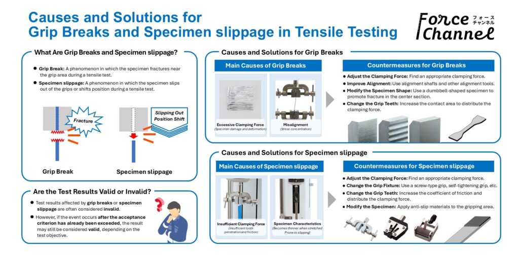
In tensile testing, problems such as grip breaks and specimen slippage are common. Many people arrive at this page wondering, “Why is the specimen slipping?” or “Can I trust the test results?” In this article, we first define what grip breaks and specimen slippage are, then explain their causes and countermeasures based on the expertise of Force Channel.
Causes and Solutions for Grip Breaks
Before discussing the causes and solutions, let us first clarify what a grip break is.
During our research for this article, we could not find any document, including ISO standards, that clearly defines the term grip break. However, in many measurement consultations received by IMADA, the term has been used to describe a situation where the specimen fractures near the grip area during a tensile test. Therefore, in this article, we define a grip break as follows:
Grip Break: A phenomenon in which the specimen fractures near the grips during a tensile test.
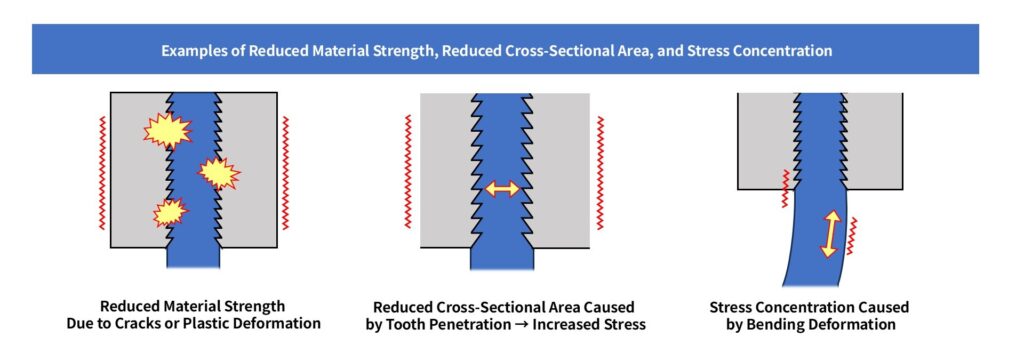
In a tensile test, fracture generally occurs where the applied stress exceeds the material strength or joint strength. In other words, if the specimen is a uniform strip, a grip break is usually caused by one of the following:
- The material strength near the grip becomes lower than that in the center section (reduction in material strength).
- The specimen cross-sectional area near the grip decreases, increasing stress until it exceeds the material strength (increase in stress).
- Uneven loading occurs near the grip, causing localized stress concentration (stress concentration).
Why do these phenomena occur?
For a typical strip-shaped specimen, the first two causes to investigate are:
- Specimen damage or deformation caused by clamping force
- Stress concentration caused by misalignment
Specimen Damage or Deformation Caused by Clamping Force
To hold a specimen securely, sufficient clamping force is necessary. However, excessive clamping force can damage or deform the specimen. As a result, material strength may decrease or stress concentration may occur in the gripping area, leading to a grip break.
Examples include:
- Serrated grip teeth penetrate the specimen surface and create localized damage (the damage becomes a stress concentration point).
- The specimen is crushed unevenly, causing a localized reduction in cross-sectional area (which increases stress).
- The specimen’s internal structure changes due to the clamping force (resulting in reduced material strength).
Typical examples include:
- Gripping an easily torn specimen with aggressive serrated jaws.
- Applying enough clamping force to create micro-cracks in the specimen.
These conditions can cause damage and stress concentration, resulting in grip breaks.
_e-1024x314.jpg)
How Can Grip Breaks Caused by Clamping Force Be Prevented?
A simple but highly effective solution is: Reduce the Clamping Force
Reducing the clamping force decreases the likelihood of damage and deformation caused by gripping.
However, reducing clamping force may increase the risk of specimen slippage, which will be discussed later. Ideally, you should find and control a clamping force that prevents both grip breaks and specimen slippage.In practice, however:
- Such an ideal clamping force may not exist.
- Even if it does, maintaining the same clamping force consistently can be difficult.
Therefore, additional approaches are often necessary.
Force Channel recommends the following three approaches:
- Increase the contact area between the grip teeth and the specimen.
- Change the grip teeth to wave-pattern teeth or urethane-faced teeth.
- Modify the specimen shape so that fracture occurs at the desired location.
Increase the Contact Area Between the Grip Teeth and the Specimen
For example, if only the tips of the grip teeth are contacting the specimen, inserting the specimen deeper into the grip can sometimes improve grip-break problems. This works because a larger contact area reduces the contact pressure (force per unit area), helping to prevent specimen damage and deformation.
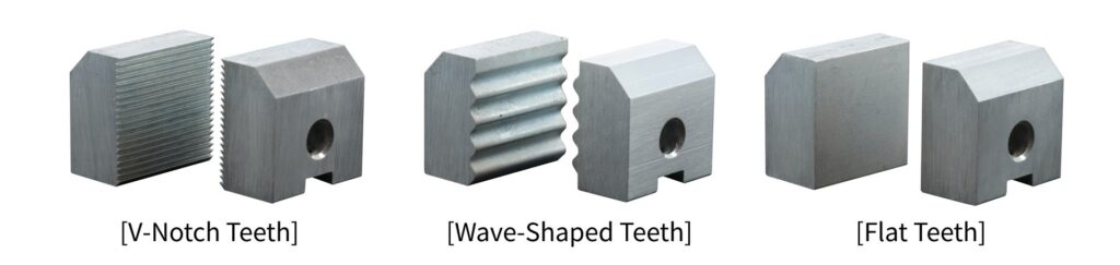
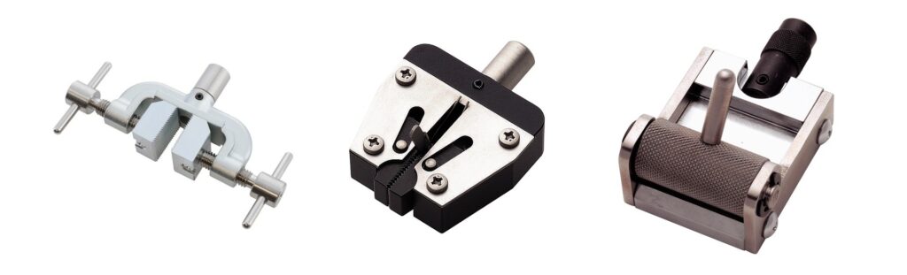
Change the Grip Teeth to Urethane-Faced or Wave-Shaped Teeth
Changing the grip tooth type is another simple and effective solution.
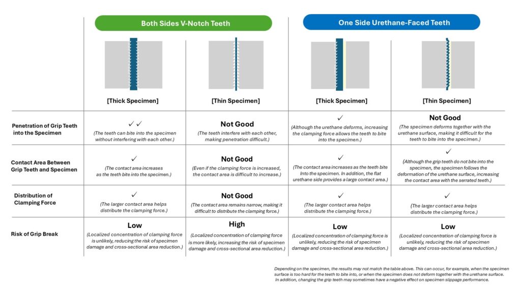
For example, when a thin specimen is gripped between two V-Notch jaws, the contact area can be very small, concentrating the clamping force in a limited region (“Both Sides Serrated” in the figure below). As a result, local pressure increases, damaging the specimen and increasing the risk of fracture originating from the damaged area.
In such cases, replacing one side with a urethane-faced jaw can help.
When one side is urethane-faced, the serrated teeth penetrate into the urethane through the specimen, increasing the effective contact area. This distributes the clamping force over a larger area and reduces local pressure (“One Side Urethane” in the figure below).
For soft materials that tear easily, such as: Paper, Fabric, and Leather, wave-shaped teeth can also be effective.
Compared with V-Notch teeth, wave-shaped teeth have a gentler contact profile. While they are not suitable for specimens that cannot conform to the wave shape, soft materials can follow the contour, allowing the clamping force to be distributed more evenly and reducing localized pressure.
Wave-shaped teeth also tend to provide better holding force than flat jaws because they still create some localized pressure points. As a result, they are often less prone to slippage than flat jaws.
(However, for materials such as aluminum foil that cannot conform to the wave shape and are prone to tearing, flat jaws may be the better solution.)
Modify the Specimen Shape So Fracture Occurs at the Desired Location
Changing the specimen to a dumbbell shape (see figure below) is a widely used method for preventing grip breaks. By reducing the cross-sectional area in the center section, stress is increased in the gauge area, encouraging fracture to occur there rather than near the grips. For this reason, dumbbell-shaped specimens are specified in many standards, including ISO standards.

Although producing identical dumbbell-shaped specimens repeatedly can be more challenging than changing grip teeth, it is one of the most effective solutions for preventing grip breaks.
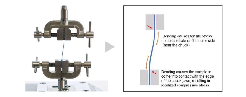
Stress Concentration Caused by Misalignment
Localized stress concentration can also be caused by misalignment.
Misalignment refers to a condition where the upper and lower grips are not aligned on the same axis. In this situation, the specimen is not pulled in a straight line relative to the grips. As a result, stress tends to concentrate near the gripping area, often leading to grip breaks.
The solution is straightforward: Reduce Misalignment
Common methods include:
- Using alignment shafts.
- Keeping the distance between the upper and lower grips as short as possible.
- Adjusting grip alignment carefully.
Differences in the angle of the gripping surfaces can also create stress concentration. Therefore, it is important to verify that both the position and angle of the gripping surfaces are properly aligned.
Summary: Grip Break Countermeasures
⚫ Reduce clamping force.
⚫ Increase the contact area between the grip teeth and the specimen.
⚫ Replace the grip teeth with urethane-faced or wave-pattern teeth.
⚫ Modify the specimen shape so that fracture occurs at the intended location.
⚫ Reduce stress concentration by improving alignment.
Causes and Solutions for Specimen slippage
Next, let us examine the causes and solutions for specimen slippage.
Specimen slippage refers to a situation where the specimen slips out of the grips or shifts position during a tensile test. Because specimen retention relies heavily on friction between the grips and the specimen, preventing specimen slippage depends largely on maintaining sufficient frictional force.
Specimen slippage: A phenomenon in which the specimen slips within the grips or shifts position during a tensile test.
In simple terms, specimen slippage occurs because frictional force is insufficient. This usually means one or both of the following conditions exist:
- The clamping force is insufficient (insufficient normal force).
- The grip surface and specimen surface are not compatible, resulting in a low coefficient of friction.
Therefore, preventing specimen slippage requires:
- Ensuring sufficient clamping force
- Reducing slipperiness
Ensuring Sufficient Clamping Force (Increasing Normal Force)
If preventing specimen slippage is the only concern, increasing clamping force is the easiest solution.
For example, when using a screw-type grip, tightening the screw more strongly increases the clamping force. However, increasing clamping force can also increase the risk of grip breaks. As discussed earlier, preventing both grip breaks and specimen slippage requires identifying and controlling an appropriate clamping force.
Special Consideration for Specimens That Become Thinner During Testing
When testing materials that stretch and become thinner, clamping force may decrease during the test.
In grips without a self-tightening mechanism, the grip opening remains unchanged as the specimen becomes thinner. As a result, clamping force decreases during the test, which can lead to specimen slippage. In these cases, grips with a self-tightening mechanism are effective because the gripping force increases as the tensile load increases.
However, keep in mind that self-tightening grips often provide lower initial clamping force than screw-type grips. If slippage occurs immediately after the test begins, grips that combine both: A screw-tightening mechanism, and A self-tightening mechanism may be the best solution.
For more information about selecting tensile grips, please refer to our related article:
Reducing Slipperiness (Increasing Friction Coefficient and Mechanical Resistance)
If adjusting clamping force alone cannot solve the problem, measures to reduce slipperiness should be considered.
Two main approaches are available:
- Change the grip tooth material or tooth profile.
- Modify the specimen so that it is less likely to slip.
Change the Grip Tooth Material or Profile
Changing the grip tooth material or shape can be an effective way to prevent specimen slippage.
V-Notch teeth are commonly used in tensile testing grips. However, if the specimen surface is hard and the teeth cannot bite into it sufficiently, the mechanical resistance provided by the teeth may be inadequate, making slippage more likely. Increasing clamping force until the teeth bite into the surface is one option, but changing the tooth material can also be effective.
Example: Change the Grip Surface to Rubber
Replacing the grip tooth material with rubber can improve friction and reduce slippage.
Changing the tooth profile is another option. For example, if flat jaws are being used because the specimen tears easily, switching to wave-pattern jaws may improve grip performance. Changes in contact area and force distribution can make slippage less likely.
Example: Replace flat jaws with wave-pattern jaws.
Modify the Specimen to Make It Less Likely to Slip
Changing the surface condition of the specimen can also help reduce specimen slippage. Examples include:
⚫ Applying anti-slip materials such as rubber sheets or paper to the gripping area.
▶ In some cases, simply inserting the material without adhesive is sufficient.
⚫ Roughening the gripping area with sandpaper.
Excessive modification may affect test results. Any modifications should:
⚫ Be limited to the gripping area.
⚫ Have minimal impact on the measurement area.
Please note that modifying only the gripping area does not automatically guarantee that test results will remain unaffected.
Summary: Specimen slippage Countermeasures
⚫ Use screw-type grips to increase initial clamping force.
⚫ For specimens that stretch and become thinner, use grips with a self-tightening mechanism.
⚫ Select grip tooth materials and profiles that match the specimen.
⚫ Apply anti-slip materials or other treatments to the gripping area.
Conclusion
In this article, we discussed the causes and solutions for the two common tensile testing problems: grip breaks and specimen slippage.
As explained throughout this article, measures that reduce grip breaks can sometimes increase the likelihood of specimen slippage, and vice versa. Therefore, it is important not to rely on a single countermeasure. Instead, combine multiple approaches to find test conditions that prevent both phenomena.
Are Test Results Valid If Grip Breaks or Specimen slippage Occur?
Finally, let us address a common question:
Are tensile test results valid if a grip break or specimen slippage occurs?
From a practical standpoint, the answer is:
In many cases the results are invalid, but the answer depends on the purpose of the test.
For example, if the objective is simply to confirm that: “The fracture load exceeds XX N” then Force Channel considers the result acceptable if the grip break or specimen slippage occurred after the required load threshold had already been reached.
However, if the objective is to determine whether: “The tensile strength falls within the range of XX–YY N/mm²” then the result cannot be used to judge pass/fail status.
Similarly, if the goal is to quantify material properties, calculations based on data affected by grip breaks or specimen slippage will generally be inaccurate and should not be considered valid. Finally, please note that the countermeasures introduced in this article assume that test conditions can be freely modified.
If test conditions are specified by:
- Industry standards
- Customer requirements
- Internal specifications
then changing grip teeth, modifying specimens, or making other adjustments may invalidate the test itself.
Before implementing any countermeasure, we strongly recommend confirming that it does not violate the required test conditions.
-300x169.jpg)